The Pressure and Furnace team have developed a humidified gas flow system for in-situ chemical reactions experiments, and presented this system at International Society for Sample Environment's 11th Workshop.
Contents:
General
The Pressure and Furnace group is continuing to support the user programme.
In-situ Chemical Reactions with Humidified Gas Flow
The Pressure and Furnace team recently presented their work with In-situ Chemical Reactions with Humidified Gas Flow at The International Society for Sample Environment's 11th Workshop, 2022.
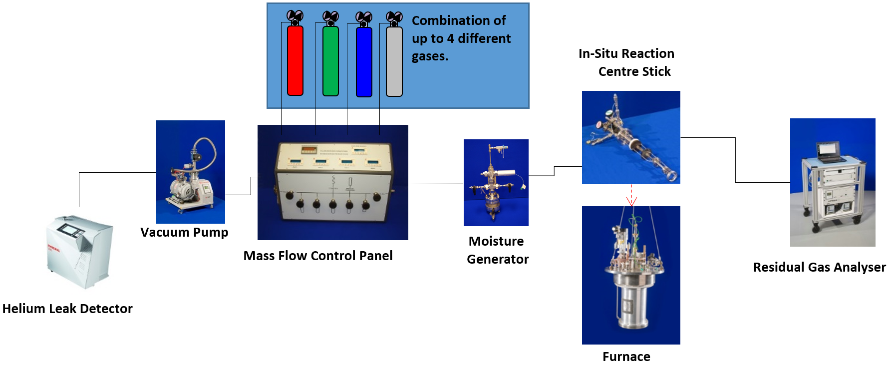
Schematic Setup of an In-situ chemical reaction experiment with humidified gas flow.
Running an experiment utilising high temperature in-situ reactions with humidified gas flow has additional requirements:
- Gas handling system with mass flow control (up to 100 sccm).
- Flow through gas cell (various pressure ratings and materials).
- Furnace (1000 °C).
- Moisture generator up to 90 °C, 15 bar.
- Residual gas analyser.
These experiments are run predominantly on the Polaris, HRPD and Osiris beam lines. This has been done for many years using humidified flowing gases. These experiments either used the in-situ chemical reaction cell or double quartz centre stick in a beamline furnace with a mass flow control panel to control the gas flow and the saturator system that was designed and built by the pressure and furnace section to provide the humidity.
Most users just want humidified gas flow and had not requested specific humidity levels. A recent request for the ability to read the level of humidity required a small project to provide this capability. The project involved Chis Goodway, Paul McIntyre and Adam Sears of the pressure & furnace section, Jacob Cooper and Ali Mortazavi of the design groups sample environment section and Keith Allum of the electronics group.
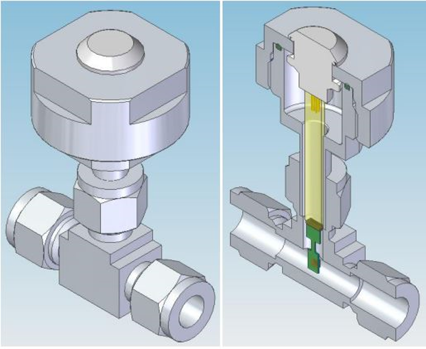
Humidity Sensor Housing
The sensor is placed between the saturator and the centre stick in the furnace. An additional sensor can be installed after the centre stick to show changes in humidity. Varying the temperature of the saturator will result in a change in the humidity levels. The gas flows from the mass flow controller, through the saturator and past the sensor.
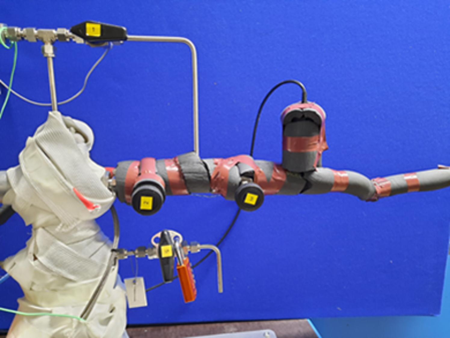
The humidity sensor housing, connected to the moisture generator.
Initial tests of humidity at set moisture generator temperatures have been very successful:
- Results repeatable.
- Controlling accurate humidity further tests required.
- Flow rate has small effect on humidity.
- Mixing humid gas with dry gas would refine control and give a lower humidity than 20%.
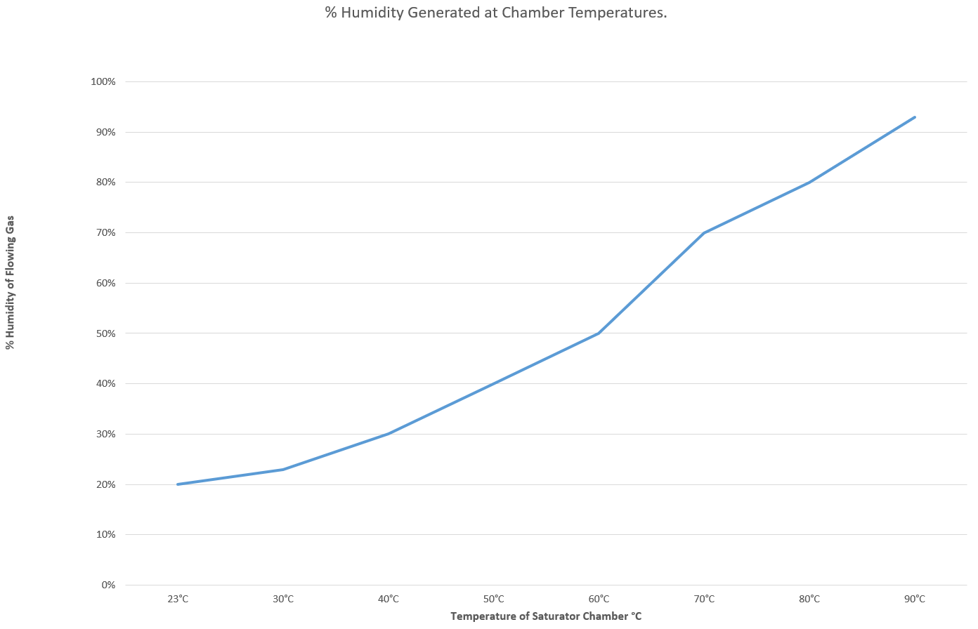
Graph of Saturation Chamber temperature vs Flow Gas humidity.
These initial tests have involved controlling the humidity by changing the temperature of the saturator. This demonstrates the proof of principle that the saturation chamber temperature can be used to control the saturation in a predictable way. Testing with the flow rate at a given temperature has shown that this has only a small effect on the humidity; the difference between 10 CCM and 100 CCM is under 3%.
By mixing the humid gas with dry gas, it should be possible to drop the humidity value below 20% and gives further control over the humidity in the range shown. Testing is continuing to refine the methodology, but it is available for use to any users who require a specific humidity during their in-situ chemical reaction experiments.
For any further details about Pressure and Furnace related topics at ISIS or anything included on this page, please
contact the Pressure and Furnace team Leader, Chris Goodway and visit the Pressure and Furnace Team
website.